CIVIL WORKS GUIDELINES FOR MICRO-HYDROPOWER IN NEPAL
89
For buried penstock sections, a minimum soil cover of 1 m
is recommended as in the case of HDPE headrace pipe, and
the trench details should be similar to those shown in Figure
4.8 (Chapter 4).
6.3 Pipe materials
In Nepal the most commonly used penstock pipe materials are
mild steel and HDPE. Rigid or unplasticised PVC (uPVC) is
another option that has been used in other countries such as
Peru (see Chapter 10, Innovations) and Sri Lanka, but has not
yet been used in Nepal. Table 6.1
The decision as to which pipe material to use for the penstock
can be based on Table 6.1, especially in Nepal. When in doubt,
it is recommended that the designer undertake preliminary
designs for all pipe materials available and compare the costs.
To minimise costs, for long penstock alignments HDPE pipes
can be used for the upstream length where the head is
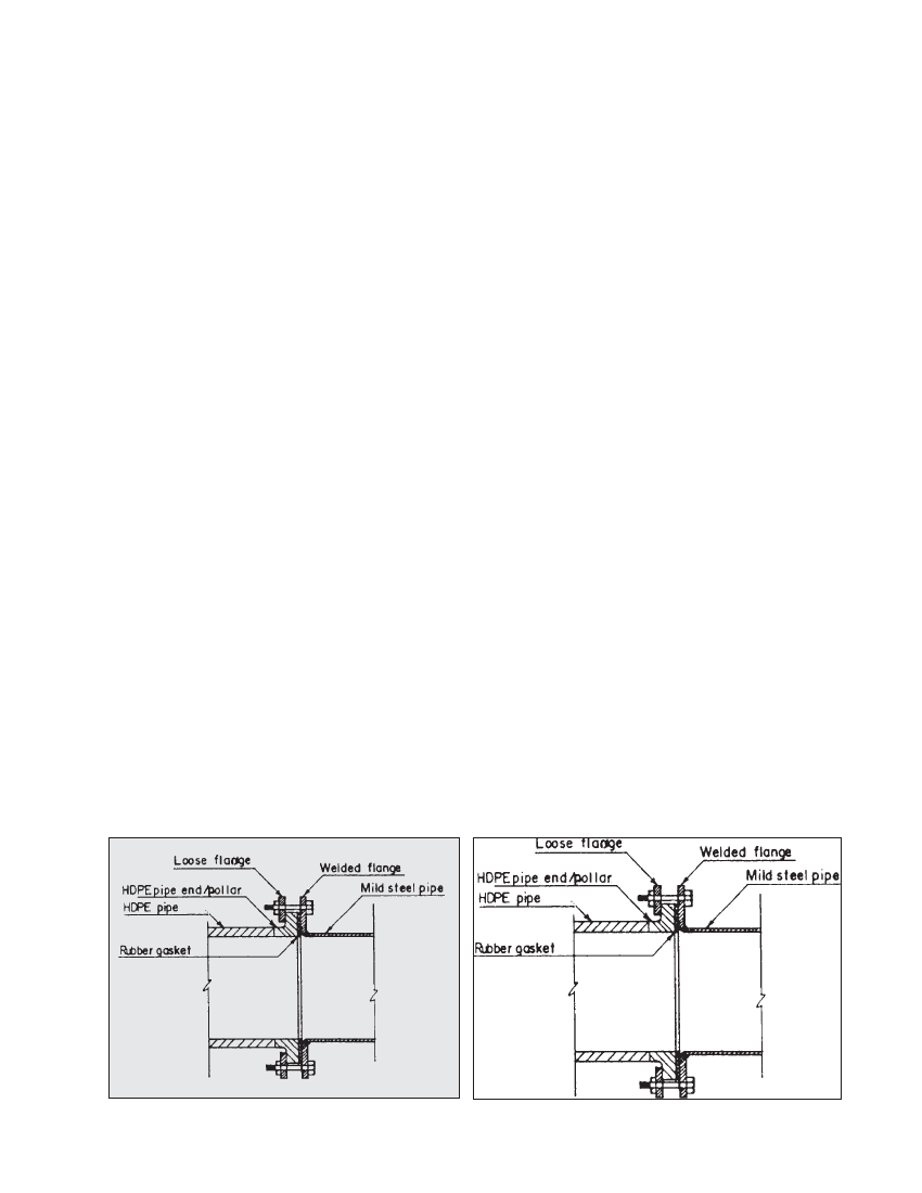
relatively low (see Box 6.1). Standard couplings are available
to join HDPE and mild steel pipes as shown in Photograph
6.6 and Figure 6.2.
Although steel pipe for micro-hydro in Nepal has normally
been specially manufactured locally, standard steel pipes may
be cheaper in some cases. Details of such pipes are given in
Appendix B.
6.4 Pipe diameter
Once the penstock alignment and pipe material have been
decided on, the design involves choosing the diameter and
pipe thickness. Selecting an appropriate pipe diameter is
discussed in this section and the wall thickness is discussed
in Section 6.6.
Note that with a few exceptions the sizing of the penstock
diameter is similar to that of a headrace pipe discussed in
Chapter 4. For simplicity, the entire penstock diameter selection
process is included in this section.
1. Choose a pipe size such that the velocity, V, is between 2.5
m/s and 3.5 m/s. In general, a velocity lower than 2.5 m/s
results in an uneconomically large diameter. Similarly, if the
velocity exceeds 3.5 m/s, the headless can be excessive and
hence uneconomical in the long run due to loss in power
output. Furthermore, higher velocities in the penstock will
result in high surge pressure as will be discussed later.
Note that compared to the headrace pipe, higher velocities
can be allowed in the penstock pipe since it conveys sediment
free water.
For steel penstocks, it may be economical to choose the
diameter so that there is no wastage from standard size
steel sheets. For HDPE or PVC, available sizes must be
selected. Pipes are normally specified by outside diameter,
so two times wall thickness must be subtracted to obtain
the internal diameter. Standard pipe sizes are given in
Appendix B.
2. Calculate the actual velocity:
V = 4Q / IId2
where:
V is velocity in m/s.
Q is design flow in m3/s.
d is the pipe internal diameter in m.
3. Calculate the headloss in the pipe length based on the
inlet, wall friction, bends, valves and exit loss as follows:
Total head loss = wall loss + turbulence losses / Wall losses
are calculated as follows: First determine the roughness value,
‘k’ in mm from Table 4.3 (Chapter 4). Then use the Moody
Chart in Figure 4.10 (Chapter 4)
Figure 6.2 Typical HPDE-mild pipe coupling
Photo 6.6 HDPE-mild steel coupling, Note that except for the final length,
the HDPE pipe is buried, Jhong micro-hydro scheme, Mustang, Nepal